

YOUR YOTTA YB-1 ESS INSTALLATION STARTS HERE
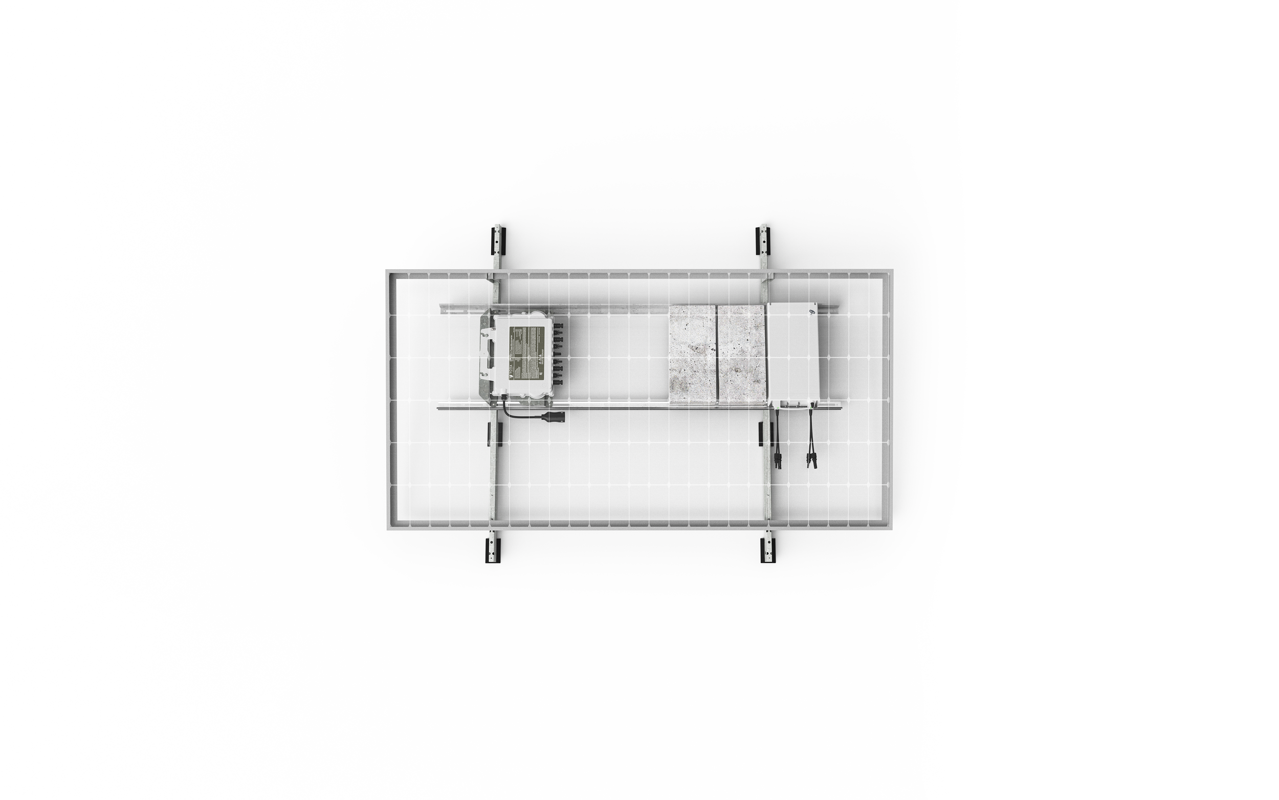
THANK YOU for choosing the YOTTA BLOCK (YB-1).
The YOTTA BLOCK (YB-1) is a PV-coupled (DC) module-level distributed energy storage unit (1kWh) with built-in thermal regulation technology, designed to minimize balance of system costs and the added complexity of installing storage alongside solar projects. It is an extension of any existing solar install using YOTTA ENERGY's DPI Microinverters — a plug-and-play solution for adding distributed energy storage within the safety of a Low Voltage (<60V) DC architecture.
Before you begin:
1. Installation and operation MUST be carried out by qualified personnel ONLY, in accordance with all safety precautions in the Installation / User Manual and all applicable local codes.
2. Outdoor commercial use ONLY. NO user-serviceable parts inside. Read ALL instructions first.
3. Not following the contents of the manual will render the warranty and any guarantees thereunder null and void.
Caution! Risk of electric shock.

All installations MUST be in compliance with all applicable regional and local codes, and other national or international electrical standards (as applicable).
The YOTTA BLOCK (YB-1) requires the chassis to be grounded. Ensure the chassis is grounded per code. Always use the existing attaching points (4) and UL2703 recognized components.
FOLLOW THE STEPS BELOW
STEP 1 — Receive, inspect, and remove the cable (PV/OUT) labels. Before anything goes on the roof…
Keep each YOTTA BLOCK (YB-1) in its original packaging until installation. Units ship at 30% SOC in "sleep" state — this is normal.
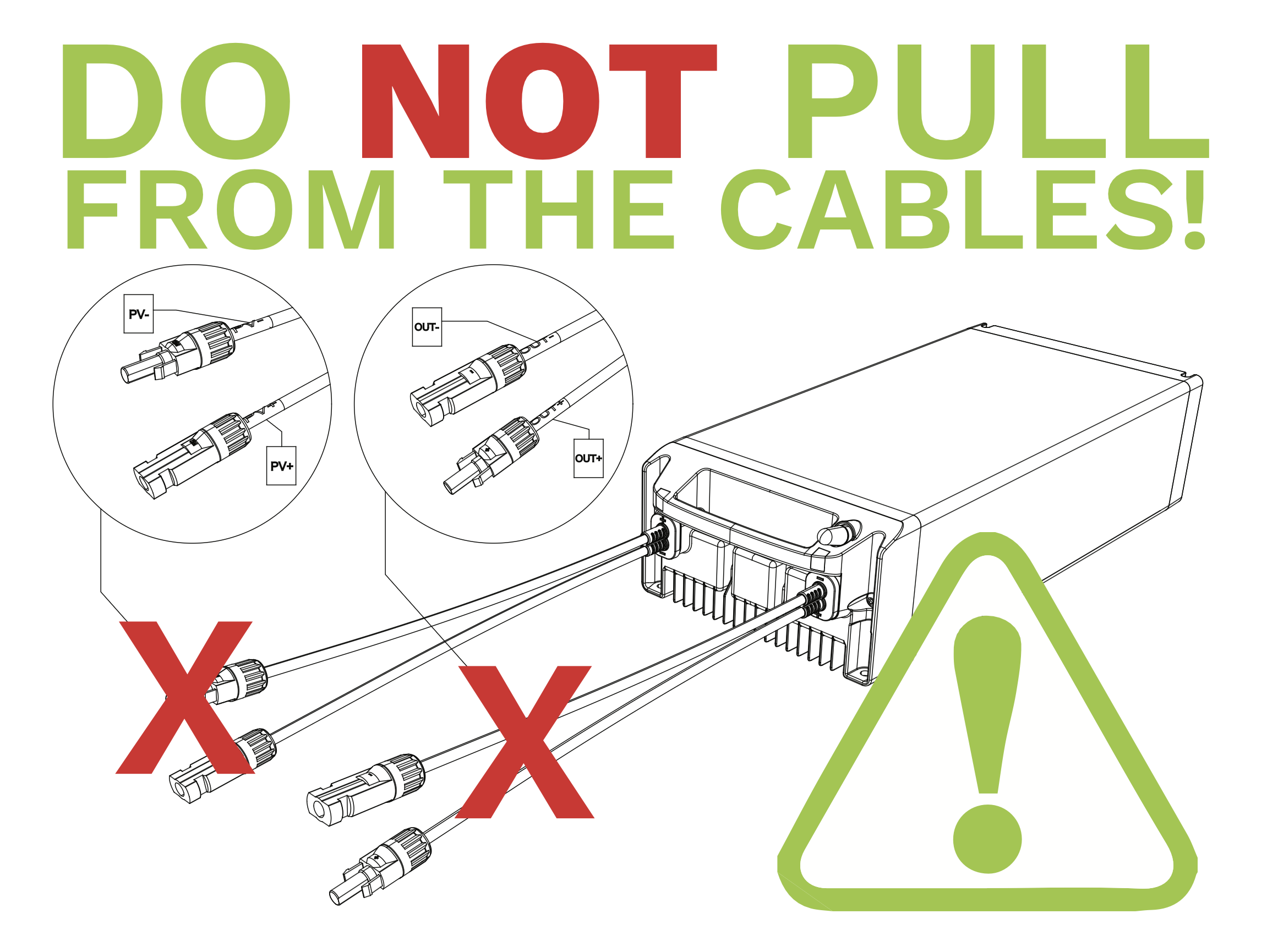
Store cool, dry, and shaded. Do NOT stack, stand on, or drop. Each unit is 28.4 lbs (12.8 kg) — lift by the integrated handle, never by the cables.
Each unit has three labels. Remove the two peel-off labels (serial + MAC) now — one goes on the PV module frame above the unit, visible without lifting the module; the second goes on the Installation Map (Appendix A).
⚠️ Removing the fixed nameplate voids the warranty. Installation by qualified personnel ONLY.
STEP 2 — Plan the layout.
Ratios and clearances before you set a single unit.
Up to four (4) YB-1 per DPI Microinverter (4:1). Pairs are the economical deployment.
≥ 48" (120 cm) between YB-1 units — per UL 9540A and NFPA 855 §15.13.
≥ 1" (25 mm) from the PV module, ≥ 2" (50 mm) from the roof. Exceptions apply by racking application.
Rail spacing should approximately match a standard ASTM C 1491 ballast block, 16" × 4" × 8". This only applies to ballasted racking systems.
⚠️ Mounting location and sun exposure must be Yotta-approved for your specific racking system. Until approved, stage units in shade — a sun shield (not included) is required for any unit in direct sun.
STEP 3 — Mount the microinverters first, then the YOTTA BLOCK
Order matters here.
Mount all DPI Microinverters and connect them to their trunk cable with AC power OFF. Do this before any YB-1 goes on the rack.
Attach the YB-1 using UL2703 recognized components and existing holes only. Do NOT drill. PanelClaw example: Yotta FR bracket P/N 310-00028, reuse two PanelClaw screws, torque 8.1 N·m (6 lb-ft).
Ground the chassis through one of the four 1/4" (6.5 mm) faceplate holes with a UL2703 recognized bonding component (e.g., ILSCO SBJ-14-18). Grounding hardware not included.
Set the unit flat and stable, DC cables facing as close as possible to the PV module and the DPI Microinverter. No pulling or mechanical stress on the cables.
STEP 4 — Connect the DC cables, then map and hand off.
You’re almost there…
GRAY TAG → output first. Connect OUT+ / OUT− to the corresponding channel of the DPI Microinverter input port.
GREEN TAG → PV input second. Connect the (+/−) DC wires from the PV module to the ports marked PV+ / PV−. This is what turns the unit on — the battery wakes automatically when it detects >15 V DC on its PV port. No further installer interaction is required.
⚠️ Wrong terminals = damage and voided warranty. Never disconnect under load. Do NOT disconnect DC OUT from the DPI without disabling power production first.
Complete the Installation Map (Appendix A) — MAC address of each YB-1 against its DPI channel. This is what YOTTA VISION commissioning runs on, and what Yotta will require for any service or replacement.
Yotta performs final commissioning at Permission to Operate (PTO). Thereafter, inspect every 180 days and after any severe weather event.